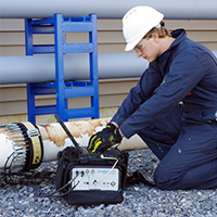
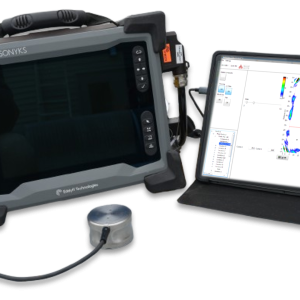
Guided Wave Phased Array Plate/Shell Inspection System
Guided Wave Phased Array – Combining the advantages of guided waves with the power of phased array
A REVOLUTION IN GUIDED WAVE TESTING
Guided waves provide the ability to inspect hidden and inaccessible regions of structures, such as structures below the ground, underwater, beneath coatings, insulation, or concrete – they also provide the ability to screen large areas of a structure from a single, remote probe position. Guided waves have enabled long-range pipe inspection technology for decades, but these capabilities need not be limited to pipes. The GWPATM technology extends long-range ultrasonic testing capabilities to plates and shells to open a wide range of applications and structures to guided wave testing – making otherwise impossible inspections possible.
The GWPATM probes utilize phased array beam steering technology to focus ultrasonic guided wave energy away from the probe and sweep this beam 360° to generate a guided wave sector scan (GS-scan). The GS-scan, which is collected and displayed in a matter of seconds, displays information on the location and extent of any flaws in the test area that reflected ultrasonic energy back to the probe. The guided wave beam steering is accomplished by utilizing an array of highly specialized guided wave sensor elements arranged in a GWPATM probe coupled with a powerful tone-burst guided wave pulser/receiver system and advanced signal processing algorithms.
The GWPATM software is designed to make data collection, organization, and analysis as simple as possible, with integrated database management, structural overlay drawings, smart artifact suppression technology, and automated composite image generation tools to compile multiple GS-scans into a single, easy-to-interpret large-area image overlaid on your structural drawing.
GUIDED WAVES – FOR PLATES
LRUT pipe inspection has proven the efficacy and benefits of guided wave testing, and now these capabilities are available for the inspection of plates – flat and curved – in carbon steel, stainless steel, aluminum, and more.
INSPECTING THE UNINSPECTABLE
GWPATM opens the door to the inspection of in-service, coated, insulated, and otherwise inaccessible or uninspectable structures where other NDE methods can’t reach. The GWPA’sTM low frequency guided wave beam extends 10 feet or more beyond the accessible probe location and can penetrate attenuative coatings, soil, and concrete.
SIMPLIFIED GUIDED WAVE PHYSICS
The 50-200 kHz shear horizontal (SH0) guided waves employed by the GWPATM probes is unaffected by liquids in contact with the structure and is non-dispersive, meaning only the shear wave speed in the material is needed to determine the guided wave velocity – no dispersion curves necessary.
EFFICIENT SCREENING OF LARGE AREAS
Electronic beam steering allows the GWPATM sensor to detect defects at distances of 10 feet or more in all directions around the probe. Each GWPATM scan can cover an area of 150 ft2 in a matter of seconds. Analysis can be performed on a single GS-scan image or by analyzing a composite image generated from a software-compiled combination of GS-scans collected at multiple test locations. The technology does not provide an exact thickness map of the structure, but it does allow the user to rapidly locate and categorize the severity of near-side and far-side flaws over a large area without the need for direct access to the inspection area and without high-density point-by-point raster scanning, which is time-consuming and can be challenging in the vicinity of obstructions and welds or on structures in which coatings or insulation limit direct access.
ROBOTIC DEPLOYMENT
Combining the GWPATM probes with a dry coupling membrane and pressure coupling device allows for robotic deployment for difficult-to-access areas including structures at height, inaccessible areas, and in-service structures. Robotic GWPATM data collection makes the most of this revolutionary technology.
SENSITIVITY BALANCED WITH RANGE
The GWPATM technology can effectively detect volumetric wall loss, including distributed and isolated pitting corrosion, as well as crack-like defects. Flaw detection range covers open plate areas as well as flaws in welds and in the HAZ, particularly when composite imaging is utilized. Pitting flaws as shallow as 10% wall loss and with pit diameters as small as 1/4-inch (6-mm) can be detected, with sensitivity decreasing with increasing distance from the probe. Factors such as coupling, plate material, and attenuation will also affect the overall sensitivity.
BENEFITS
- Guided wave inspection of inaccessible areas, coated, insulated, and buried sections of plates
- Efficient large-area screening of plates and shells
- Applicable for carbon steel, stainless steel, aluminum, and nearly all metallic alloys
- Applicable for flat and curved plates up to 1-inch (25-mm) thick
- Detection of near-side and far-side flaws
- Unaffected by liquids in contact with structure
- Simplified guided wave mode for ease of use
- Drawing overlay to easily correlate data with the real structure
- Composite imaging for easier data interpretation
- Robotic deployment for maximum coverage and efficiency, even in limited access situations
Rapid Large Area Inspection from a Single Sensor Position: A Guided Shear Wave Phased Array Scan – Materials Evaluation
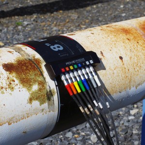
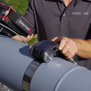
Guided Wave Phased Array Probes
Learn More