Guided wave pipe inspection is the most prominent application of guided waves in NDT. This is because it offers rapid screening capabilities and can provide inspection data for inaccessible sections of pipe such as insulated, coated, or buried lines and corrosion at supports. Guided wave pipe inspection is practiced around the world.
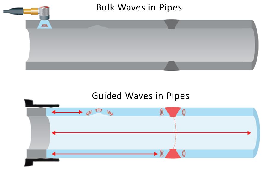
Guided waves in pipes rely on the outer diameter (OD) and inner diameter (ID) surfaces to propagate long axial distances in the pipe wall; therefore the diameter and schedule (thickness) of the pipe and the material of which it is constructed will determine the characteristics of the guided waves that it may support. The properties of guided waves in pipes are more heavily affected by the pipe diameter than the pipe schedule. In fact, the properties of guided waves in plates are often described in terms of the frequency-diameter (fD) product. For instance, many of the properties of a 60-kHz guided wave in an 8”-diameter pipe are similar to those of a 30-kHz guided wave in a 16”-diameter pipe; note that the fD product for both of these cases is 480 kHz-in.
Two types of axial guided waves exist in pipes: longitudinal (L) and torsional (T). While not identical to the Lamb and SH waves that occur in plates and shells, they are generally analogous to them, respectively. Just as with guided waves in plates and shells, multiple modes may exist for either an L-type or a T-type wave in pipes, but due to the cylindrical geometry of pipes, another layer of mode complexity exists, in which families of modes exist that are associated with each L or T wave.
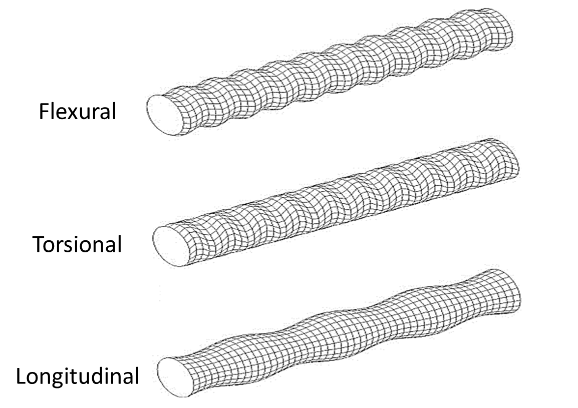
The primary member of each mode family is the axisymmetric L or T mode, which has uniform energy distribution around the circumference of the pipe (think of this as a uniform ring of energy being sent down the pipe). The other members of each mode family are flexural modes, which are guided waves that spiral down the pipe at some angle to the pipe’s axis, which means that their energy is not uniformly distributed around the circumference of the pipe. While defect detection can be performed with the fundamental axisymmetric modes in a pipe, advanced focusing and analysis applications require a knowledge and utilization of the flexural modes as well.
Fortunately, most of this complexity is handled automatically by the software and only a general understanding of the wave properties is required for the user to perform a successful inspection; this is the case with all of the long-range piezoelectric and long-range magnetostrictive pipe NDT and SHM systems offered by Guidedwave. Long-range guided wave pipe inspection is a powerful tool for rapid screening of long sections of pipe, sometimes up to 600’ of pipe at once. Guided wave long-range pipe inspection is a well-accepted technique that is deployed worldwide, and ASNT is in the process of developing its own certification criteria for this technique.
In addition to long-range pipe inspection applications, guided waves can also be used for short- or medium-range applications. For instance, guided waves can be used to detect corrosion in inaccessible areas such as pipe supports, elbows, and within close proximity to large structural features like flanges, T’s, etc., which may be difficult for long-range systems. Another advantage of short-range systems is that that generally offer much higher sensitivity and resolution. The MRUT scanner offered by Guidedwave uses higher-frequency guided waves (in the 125 kHz range) to rapidly generate high-resolution two-dimensional scans of an area of a pipe. This system can be applied to structures ranging from 4”-diameter pipes to larger-diameter pipes to pressure vessels to flat plates.

Guided waves can also be transmitted circumferentially around a pipe for special applications such as pigging or in-line inspection (ILI). Using this configuration, guided waves are sent part-way or all the way around the circumference of the pipe to inspect the pipe for defects and damage or to detect coating disbonds. In an ILI configuration, the sensor system is automatically moved along the length of the pipe through its interior.